Understanding externalTrafficPolicy and internalTrafficPolicy in Kubernetes
You have probably seen the externalTrafficPolicy or internalTrafficPolicy field in a Service manifest before. But what exactly are they and what are they used for?
In this post, we will visually understand these two parameters and their role in traffic balancing.
externalTrafficPolicy
This field, commonly seen in LoadBalancer Services such as those created by Ingress Controllers like ingress-nginx and Traefik, controls how traffic coming from outside the cluster is distributed among Pods. It has two possible values:
Cluster(Default): External traffic is balanced across all Pods on all Nodes, regardless of which Node the traffic first arrived at.Local: External traffic is balanced only to Pods running on the same Node where the traffic entered the cluster.
externalTrafficPolicy: Cluster
As an example, take a look at the video below showing how a packet is balanced in a cluster containing:
- 3 Nodes: VM1, VM2 and VM3 (we will ignore Node VM2, assuming it failed the load balancer health check).
- A Network LB created from a
LoadBalancerService present in the cluster (configured withexternalTrafficPolicy: Cluster). - 3 Pods, where one is on Node VM1 and the other two are on Node VM3.
Journey of a packet from the client to the Pod when using externalTrafficPolicy: Cluster. Source.
Putting the video above into words:
- The packet reaches the LB, which forwards it to one of the Nodes (highlighted in green). At this point, the LB only sees the Nodes and knows nothing about the state of the Pods, their distribution, the Kubernetes cluster itself, etc. Its job is purely to balance requests between the machines behind it.
- After selecting the Node (
VM1), the LB sends the packet, which then goes through a set of iptables rules upon arrival. These rules are managed by kube-proxy, which runs as a DaemonSet and therefore has one replica per machine. Since we are using Cluster mode, the iptables rules will balance the request across all existing Pods, regardless of which machine they are running on. pod2on NodeVM3is selected, and the packet goes through the NAT process, causing an extra network hop due to the balancing performed between all Pods in the previous step by iptables.- After the packet reaches its destination at
pod2, the reverse path begins, with the packet returning to NodeVM1. - Once the packet reaches Node
VM1, the NAT is undone with the help ofconntrack, which keeps a table containing the changes previously made by NAT. - With the NAT reverted, the packet heads back to the client that made the request, passing through the LB in the process.
externalTrafficPolicy: Local
Now let’s see how balancing works when using externalTrafficPolicy: Local, with the following scenario:
- 3 Nodes: VM1, VM2 and VM3 (we will ignore Node VM2, assuming it failed the load balancer health check).
- A Network LB created from a
LoadBalancerService present in the cluster (configured withexternalTrafficPolicy: Local). - 3 Pods, where one is on Node VM1 and the other two are on Node VM3.
Journey of a packet from the client to the Pod when using externalTrafficPolicy: Local. Source.
- The packet reaches the LB, which forwards it to one of the Nodes (highlighted in green). Since
VM2failed the LB health checks in this example, it cannot be selected. - Node
VM3is selected and the packet arrives at the machine, where it goes through iptables. Unlike the previous example, because we are using theLocalconfiguration, the packet will only be balanced between the two Pods present on NodeVM3(pod2andpod3). - With
pod2selected, the packet goes through DNAT, having its destination changed topod2. - The packet reaches its destination and starts its return path, with the NAT being undone with help from
conntrack. - The packet leaves Node
VM3towards the client, passing through the LB in the process.
Differences between Cluster and Local
Cluster
- The client IP is lost.
- Traffic is correctly balanced across all Pods.
- May cause an additional network hop during the request path (potentially increasing latency).
Local
- The client IP is preserved.
- Depending on Pod placement and quantity across Nodes, traffic may become unbalanced between Pods.
- No additional network hop during the request path.
Considerations when choosing Local mode
When using Local mode, external traffic arriving at a Node is forwarded exclusively to Pods hosted on that same Node. Since external load balancers usually distribute traffic evenly across Nodes (and not Pods), there is a significant risk of uneven traffic distribution unless the workload is a DaemonSet or uses strict podAntiAffinity or topologySpreadConstraints rules.
For the scenarios below, traffic distribution will remain balanced (similar to Cluster mode):
- Number of Pods much greater than the number of Nodes.
- Since there is a large number of replicas, the Kubernetes scheduler will distribute the Pods relatively evenly among the available Nodes. Even if one Node ends up with a few more Pods than another, the large total volume of replicas dilutes the difference, making the load received by each individual Pod remain close to an acceptable balance.
- Number of Nodes much greater than the number of Pods.
- In this scenario, the probability of the same Node hosting more than one Pod is minimal. Since each active Node will only have one Pod (behaving, in practice, as if it were a DaemonSet on those specific Nodes), the traffic distributed across the Nodes will result in perfectly balanced traffic between Pods.
However, in the following scenario:
- Number of Pods close to or equal to the number of Nodes.
A large traffic imbalance may occur, since the scheduler may end up grouping multiple Pods on some Nodes while leaving other Nodes with only a single replica (singletons).
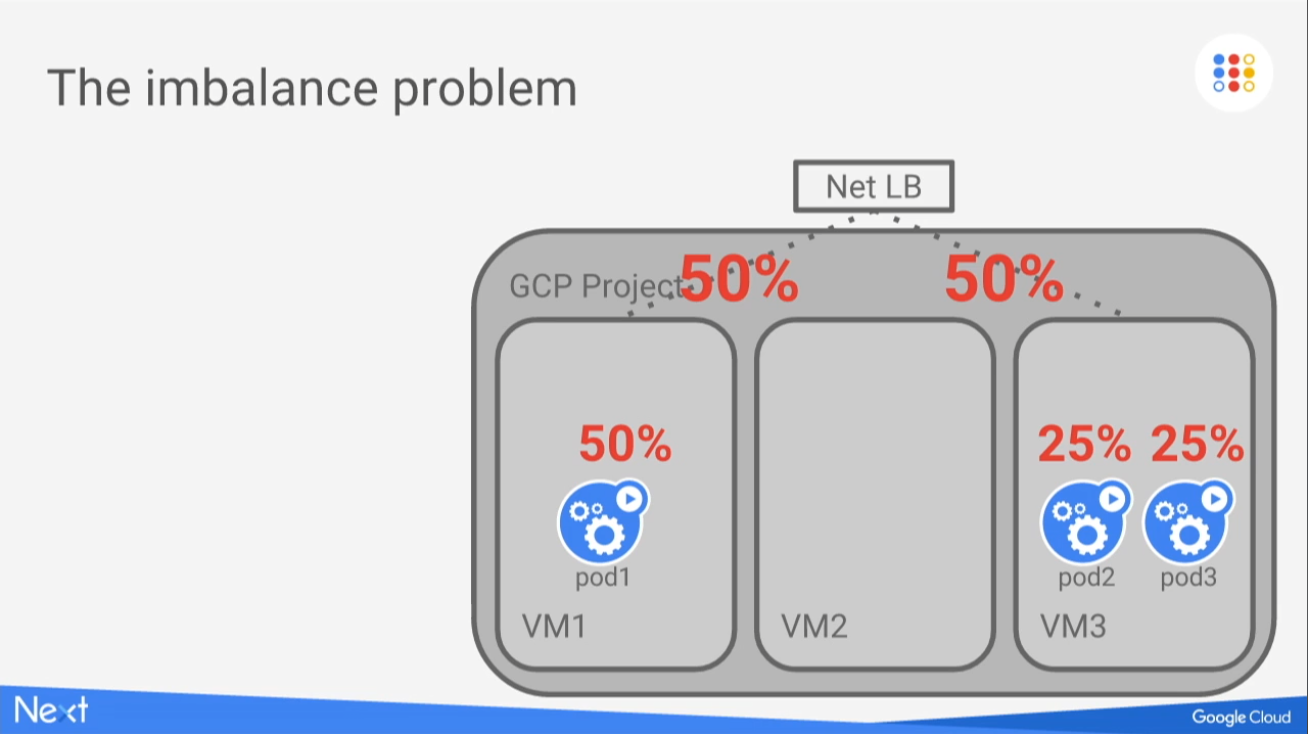
A number of Pods similar to the number of Nodes may create traffic imbalance if the workload is not a DaemonSet or if podAntiAffinity or topologySpreadConstraints rules are not used. Source.
Balancing traffic to Nodes without Pods
In the previous examples, it was mentioned that Node VM2 would not be considered because it had “failed the load balancer health check”. But what does that actually mean? Imagine the following scenario:
- A
LoadBalancerService configured asLocal. - Node VM2 is considered eligible to receive packets.
- A packet reaches the LB, which forwards it to Node VM2, which has no Pods.
- The packet reaches the machine, but there are no Pods available. Additionally, it cannot be forwarded to Pods on other Nodes because we are using
Localmode.
So what happens then? Is the packet simply dropped and the client receives a timeout?
This is exactly the case that the load balancer health check helps avoid. In LoadBalancer Services, there is a parameter called healthCheckNodePort, which defines the port used for health checks:
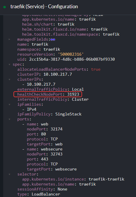
healthCheckNodePort, highlighted in the image, defines the port used by the health checks performed by the load balancer on the AWS side.
On the AWS side:
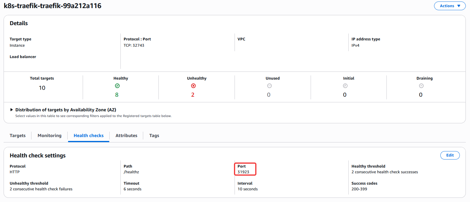
Just like in the manifest, port 31923 also appears in the AWS console.
The LB frequently sends HTTP requests to all Nodes on port 31923, using the /healthz path.
We can confirm that this port is actually exposed by running the ss -tlnup command on one of the cluster Nodes:
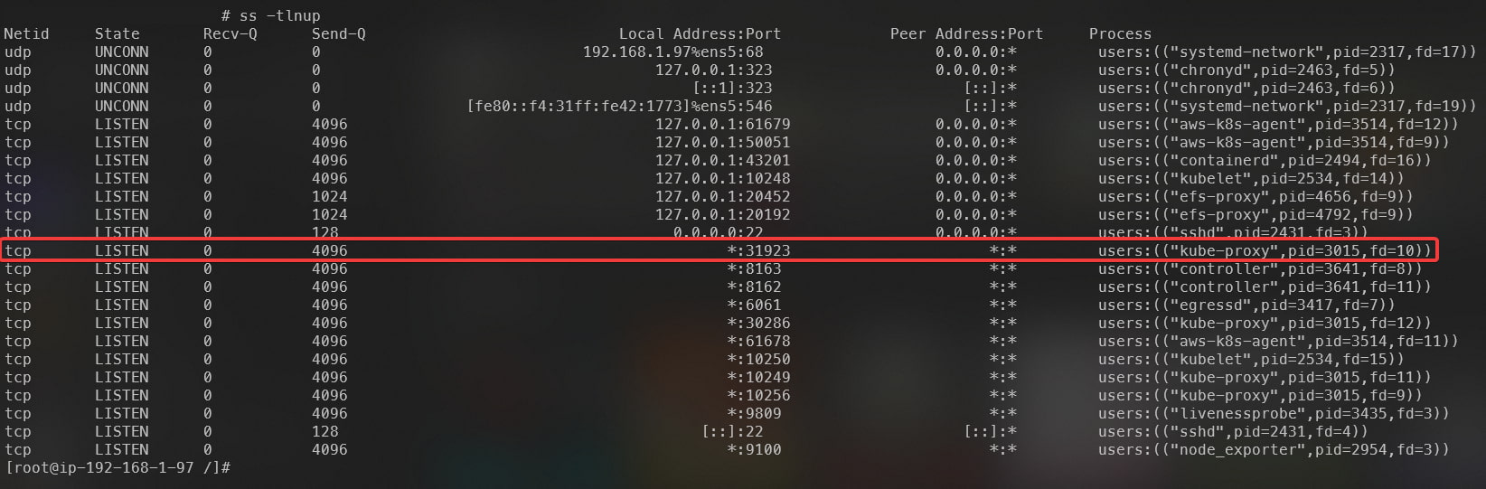
Highlighted kube-proxy process, responsible for responding to requests arriving at the localhost:31923/healthz endpoint.
The kube-proxy process is responsible for responding to incoming requests, and as we saw earlier in the AWS console, the path used is /healthz. We can therefore test this endpoint by sending a cURL request from one of the Nodes to localhost:31923/healthz, obtaining the response below:
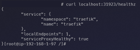
JSON response returned when requesting the health check endpoint.
The response is simply a JSON containing the name and namespace of the service associated with the LB, along with the following fields:
localEndpoints→ When usingexternalTrafficPolicy: Local, returns the number of Pods related to the service associated with the LB (Traefik in this case) present on the current Node. Since this Traefik installation is running as a DaemonSet, we have one Pod per Node (except for two Nodes in this cluster that contain taints).serviceProxyHealthy→ Returnstrueif kube-proxy is healthy (process running and iptables rules properly synchronized with the kernel, ensuring there is a valid path to reach the service endpoint associated with the LB).
Since this Node has at least one Traefik Pod (localEndpoints >= 1) and kube-proxy is running correctly with synchronized iptables rules, it is marked as healthy and becomes eligible to receive external traffic.
Health checks when using externalTrafficPolicy: Cluster
When switching to Cluster mode, it is possible to notice in the Service manifest that the healthCheckNodePort field disappears:
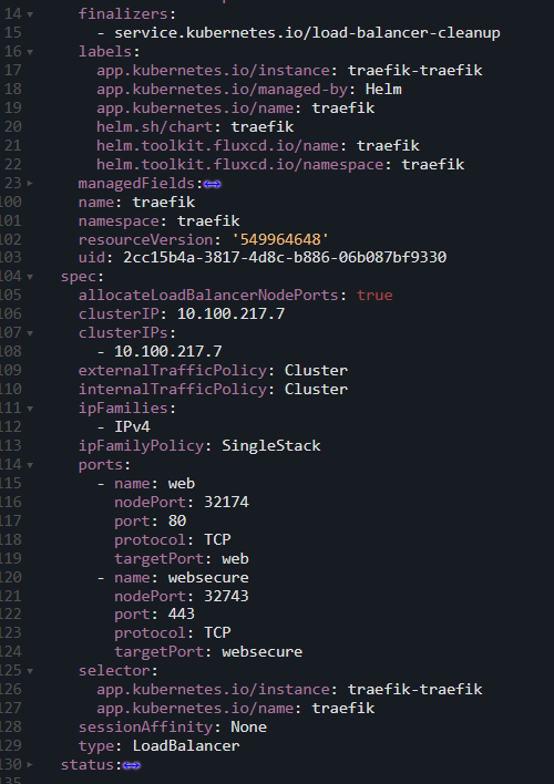
Manifest of a Service using externalTrafficPolicy: Cluster, changing how the health check is performed and, as a consequence, removing the healthCheckNodePort field.
On the AWS side, we can see that:
- The protocol used for the health check changed from HTTP to TCP.
- The
/healthzpath is no longer used (since the protocol is now TCP). - The port used for the health check is the same port where the Node accepts client requests (32174).
- The number of Nodes marked as healthy increased from 8 to 10, even though there are still only 8 Traefik Pods in our cluster.
- Other configurations such as interval, timeout and thresholds were also modified.
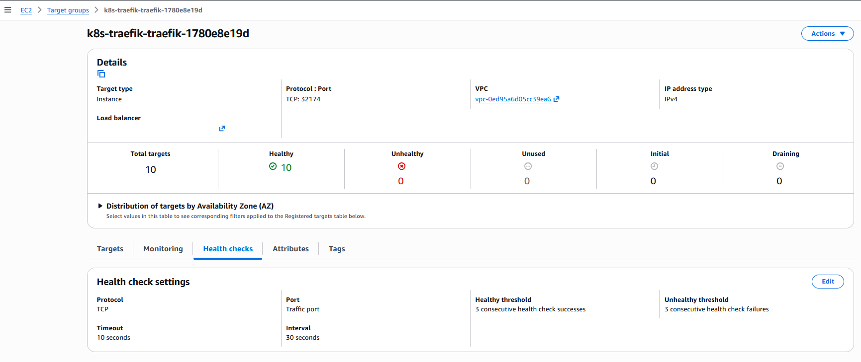
Health check settings menu for one of the load balancer Target Groups after changing to externalTrafficPolicy: Cluster.
Testing directly on the Node, we confirm that the previously used port 31923 is no longer open:

Since the way health checks are performed changed, the kube-proxy process responsible for responding to this type of request is no longer running.
However, this creates another question. This environment has 10 Nodes, 2 of which contain taints. Since Traefik, the service we are using as an example, is installed as a DaemonSet (without tolerations for these taints), we only have 8 replicas. If the number of healthy Nodes considered by the LB increased from 8 to 10, how is that possible if the number of Traefik replicas remains the same?
The answer lies in how the health check works when using Cluster mode. Since traffic is balanced between all Pods regardless of which Node they are on, traffic may arrive at a Node that does not contain any Traefik Pods, where the iptables rules will then forward the traffic to a Pod running on another Node. Because the health check uses the same port through which normal traffic flows, it follows the same path and is always able to reach a Traefik Pod, even if the Node where the traffic initially arrived has no Pods.
internalTrafficPolicy
This configuration follows the same logical principle as externalTrafficPolicy, but with a different scope: it exclusively manages the routing of internal cluster traffic (that is, requests originating from other Pods and internal services).
Another important point is that internalTrafficPolicy can be used with other Service types such as ClusterIP, and not only with LoadBalancer and NodePort.
The configuration accepts the same two values to define balancing behavior:
Cluster(Default): Internal traffic is balanced across all Pods on all Nodes, regardless of which Node the traffic originated from.Local: Internal traffic is balanced only to Pods present on the same Node where the traffic originated.- If a Pod attempts to access a Service in
Localmode and there is no replica of the target Pod running on its own Node, the packet will be dropped.
- If a Pod attempts to access a Service in
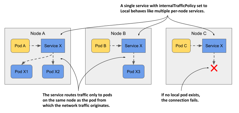
How connectivity between Pods works through a Service configured with internalTrafficPolicy: Local. Source.
Conclusion
I hope this post helped you better understand how externalTrafficPolicy works. Although it may seem like a difficult concept at first, a good visual explanation is enough to show that it is actually quite simple to understand.
Finally, I recommend watching the presentation The ins and outs of networking in Google Container Engine and Kubernetes, which not only contains an excellent explanation of how networking works in Kubernetes, but also explains externalTrafficPolicy in greater detail (the videos and some examples used in this post were taken from that presentation).